Designing your OPC 1: the laser
When designing an OPC, one of the first things you will probably consider is the desired performance. What size range can I measure?
This is quite a complex question to answer, but it depends primarily on three key components: the laser, the photodetector, and the data acquisition (DAQ) system. For the laser, the intensity/power and the wavelength determine the amount of light scattered into our photodetector. For the photodetector, the sensitivity at the laser wavelength, and the total conversion gain (Volts per Watt of light) determine the smallest and largest voltage signals you can get from the scattered light. The resolution of the DAQ system then determines the minimum voltage signal you can actually measure.
Of course there are other factors in an instrument which influence the size range, for example:
- – Optics (Over what angles do we collect the scattered light? How well is the light focused on the photodetector?)
- – Additional signal conditioning (Signal amplification? Filters?)
- – Min/maximum voltages measurable by system
However those three key components are the main factors and are the focus of this series of blog posts – specifically how they interact and how one might start to arrive at an optimal configuration. This post will specifically focus on choosing a laser, and the main requirements.
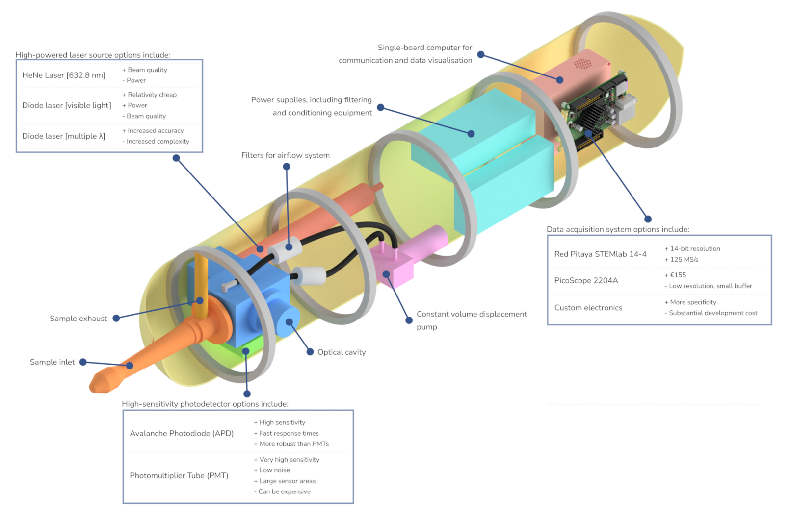
The laser is the source of the light scattering off the particles, which is collected by the photodetector. For that reason, the wavelength of the laser needs to match the responsivity spectrum of the photodetector – more on that later. The wavelength also influences the sizes of particles you can measure, due to the scattering properties. Where the particle diameter is approximately less than the wavelength of the laser, Rayleigh scattering occurs. Where the diameter is comparable to or greater than the wavelength, Mie scattering is the appropriate theory.
This means that for small particles, <= 300 nm, there can be orders of magnitude difference in the scattering cross section. For example, as you can see below, for a particle of 100 nm, there are two orders of magnitude between the scattering cross section with a 400 nm laser, and a 1310 nm laser. 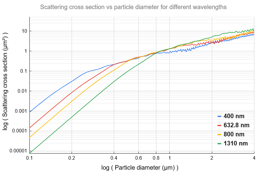
This plot uses simulated Mie scattering data, from code authored by Phil Rosenberg.
Essentially, as scattering cross section determines the amount of light scattered by an incident laser on a particle, it would be easier to detect a small particle with a lower wavelength laser. This plot also highlights what probably ends up being the trickiest part of measuring a certain range in particle sizes – the significant dynamic range needed in a sensor to measure up to five or six orders of magnitude difference in particle scattering cross sections, if you want to continuously measure sizes from around 100 nm up to several microns! So the lower wavelength the better, with two main caveats: can you get a detector which is sufficiently sensitive at those wavelengths; and can you get a laser of sufficiently high power?
The power is somewhat simple – the more the better (up to the point at which you start to melt your optics and/or influence the particles). Scattered light from a given particle increases linearly with laser power – so a 500 mW laser will give 10x more scattered light than a 50 mW laser. It’s therefore tempting to go high – multiple Watt laser diodes can be bought relatively cheaply, and are simple to operate. However, the beam quality is important and limits the ease of achieving a high power – multi-mode diodes are unlikely to be suitable.
The beam profile: laser beams have various transverse modes, aka the intensity profile perpendicular to the axis of propagation. This is of interest to us as it’s the profile a particle will experience as it crosses the beam in our instrument, and can be used to predict the scattered light. ‘Single-mode’ lasers (meaning in this case, single transverse, or TEM00 lasers) have a Gaussian intensity profile, and usually a narrow beam diameter; while multi-mode lasers have a number of modes which aggregate into a roughly ‘top-hat’-shaped profile and generally a larger beam diameter. This source has some useful information on the different beam profiles. The differences tend to be due to differences in the physical architecture of the lasers themselves.
Some sources state that single-mode laser beams are necessary for an OPC: The laser beam intensity profile may be considerably less predictable and consistent for a multi-mode beam, when compared to a single-mode beam which has a purely Gaussian profile. This could make an instrument exceedingly difficult to calibrate, with scattered light from a given particle changing minute-to-minute. Beam diameter is also quite relevant. A smaller diameter for the same power means a higher intensity, particularly for Gaussian beams where the peak intensity in the middle of the beam will be approximately twice the average intensity. A smaller diameter means the transit time of a particle through the beam is shorter, and it might make alignment harder. A larger diameter might mean that, if you can focus the particles to a thin enough stream (200 µm, for example), they experience a more consistent intensity profile (imagine a particle passing through the center peak intensity part of the Gaussian curve, versus one missing the center and passing through some distance to the side – for a really narrow Gaussian, the difference in intensity could be 50% or more), making the instrument more precise.
Most OPCs appear to use single-mode lasers, however this makes achieving ‘high’ laser powers difficult – single-mode diode lasers can be found up to 200 mW or more, but higher is unlikely. Diode lasers are relatively simple to operate, cheap, and reliable, being solid state devices. Single-mode lasing of >500 mW can be achieved using other technologies such as Diode-Pumped Solid State lasers, but complexity and cost can increase substantially.
The PCASP (the ‘parent’ instrument of our CRROPC) used a HeNe laser of less than ~100 mW, but utilises an oscillating mirror such that the particle interactions happen within the laser cavity, where intracavity power is considerably higher than the nominal output power. The oscillating mirror however can be fragile, experiencing issues during vibrations or changes in orientation, and alignment is complex.
We’ve opted to buy an ‘optically pumped semiconductor laser’ (OPSL) from Coherent – which basically uses a high-power diode laser to pump a semiconductor. Our laser operates at 577 nm, and ~3 W – with a beam diameter between 1 – 1.5 mm. The extra power gives some extra leverage in measuring smaller particles, although the power consumption and heat generation are high.
More on selecting components in the next post!
Benjamin Rae